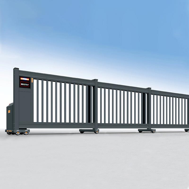
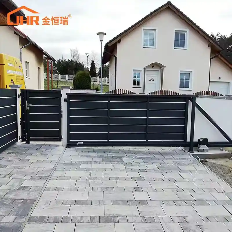
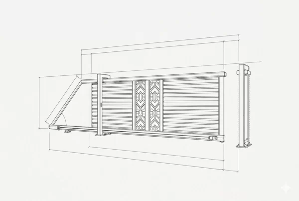
Up to 25 meters clear span, side clearance cut by up to 50%
The panel system is what makes the math work. Three sections covering a 20-meter opening each travel roughly 7 meters — the combined retracted stack occupies 8 to 9 meters of side wall. A single panel covering the same opening would need all 20 meters to retract into.
2 to 5-section configurations, 6 m to 25 m opening width
Section count scales with the opening width and the available side clearance on the specific site. Wider spans with tighter retraction zones use more sections. The engineering team works from your actual wall dimensions to determine the configuration.
Reinforced 6063-T5 aluminum alloy frame throughout
Not the decorative-grade aluminum used in residential products — the reinforced profile specification for structural load at industrial span widths. 40% lighter than mild steel at the same cross-section, which matters when that weight is distributed across multiple sections and multiple roller assemblies.
Dual or triple parallel ground tracks, sealed-bearing rollers
Each section runs on its own track. The tracks are what keep the panels aligned during travel — if one panel drifts laterally, the coupling to the next section introduces binding. Track installation accuracy is the critical variable on a telescopic gate, which is why JHR supplies a precision alignment template with every order.
High-torque motor, 24V DC or 220V / 380V AC, soft-start / soft-stop
Multiple panels accelerating together require a drive unit sized for combined inertia, not single-panel load. Soft-start prevents the coupling brackets from taking the full panel inertia as a shock load on each cycle. Soft-stop matters at both ends of travel — the lead panel and the trailing sections need to decelerate together, not arrive at the end stop in sequence.
RF remote, RFID, keypad, loop detector, BMS — all supported
Same control interface range as the JHR cantilever and retractable product lines. Specified at order; no modification to the gate frame is required to accommodate any of these.
Power Failure or High Temperature Protection
In case power failure,the gate can be manually controlled. And there is also over-heated protection up to75degree, the motor will stop automatically till the temperature comes normal.
The Engineering Logic Behind Telescopic Nesting — and Where It Can Go Wrong
The nesting mechanism is straightforward in principle: shorter panels on parallel tracks, stacking at the open position instead of one long panel travelling the full width. In practice, the variable that determines whether a telescopic gate runs well long-term is inter-panel coupling accuracy.
Each panel junction has a coupling bracket that links the leading edge of the inner section to the trailing edge of the outer section during travel. When the motor drives the outer panel, the bracket transmits that motion to the inner panel at a fixed ratio. If the bracket has play in it — from manufacturing tolerance, from wear, or from a track that isn’t perfectly level — that play shows up as lateral drift between sections. The panels don’t travel in perfectly parallel lines; they develop a slight angular offset. Over time, that offset loads the rollers unevenly. One side of the roller carriage wears faster than the other. The panel starts to drag on that side. The motor current climbs. The maintenance call comes in.
JHR machines the coupling brackets to tight tolerance and supplies the track alignment template specifically because that’s where the majority of telescopic gate problems originate — not in the motor, not in the panels themselves, but in the inter-panel connection and the track geometry underneath it. Getting the installation right the first time is cheaper than correcting drift after the gate has been running for six months.
Soft-start and soft-stop on the motor serve a related function. When multiple panels decelerate at the end of travel, the outer panel arrives at the end stop first. If the motor stops abruptly, the inner panels are still carrying momentum and the coupling brackets absorb that as a shock load. Over thousands of cycles, those shock loads loosen the bracket fasteners and introduce the play that causes the drift problem above. Controlled deceleration keeps the panels arriving at their end positions in a managed sequence rather than a chain-reaction collision.
Why Aluminum on a Multi-Section Industrial Gate
The weight argument for aluminum is more consequential on a telescopic gate than on a single-panel design because the multiplication effect works against steel.
A 5-section telescopic gate covering 25 meters has six or more roller assemblies — two per section, sometimes four on larger spans — each carrying the dead load of the panel above it. That load doesn’t change between cycles; the bearings are supporting it continuously, whether the gate is moving or sitting stationary. Rolling resistance under that sustained load is what determines how quickly the bearings wear down to the point where alignment drift becomes noticeable.
At 40% lighter than mild steel across the same structural cross-section, the aluminum panels reduce that continuous bearing load from day one. The motor operates within a wider margin of its rated capacity on every open-close cycle. Bearing service intervals extend. The track surface wears more slowly under the lighter roller load. Those aren’t dramatic differences you see in the first year — they’re the kind of differences that show up in a maintenance log over five or ten years of daily operation.
The corrosion point is simpler. Steel telescopic gate frames rust at the weld lines and at the roller contact points — the same places where coating coverage is thinnest and where water sits after rain. Once rust develops at a roller contact point, the rolling surface is no longer smooth, resistance increases, and the problem accelerates. The 6063-T5 aluminum frame doesn’t have weld-line corrosion; the surface coating goes on over a chromate conversion primer that bonds properly to aluminum substrate, unlike direct-to-steel powder coat which can lift at unprepped edges. The frame looks the same in year ten as it did at installation, without recoating.
Product Specifications
Technical Item
|
Specifications & Details
|
| Gate Type |
Industrial Telescopic Sliding Gate (2 to 5-section nested panels) |
| Frame Material |
Reinforced 6063-T5 Aluminum Alloy profiles |
| Surface Finish |
Chromate primer + industrial powder topcoat; standard or custom RAL colors |
| Maximum Clear Span |
Up to 25.0 meters (standard range 6 m – 25 m) |
| Gate Height |
1.5 m to 2.4 m (customizable to site requirement) |
| Side Clearance Required |
Approximately 40–50% of clear span (vs 100% for single-panel sliding gate) |
| Section Configuration |
2 to 5-section nested panels; each section on independent ground track |
| Track System |
Single ground tracks with heavy-duty sealed-bearing rollers |
| Drive System |
High-torque industrial sliding gate motor, 24V DC or 220V / 380V AC; soft-start / soft-stop standard |
| Control Options |
RF remote (up to 50 m), RFID reader, PIN keypad, inductive loop detector, intercom, BMS integration (RS485 / dry contact) |
| Smart Compatibility |
Compatible with major smart access platforms and industrial building management systems |
| Safety Features |
Infrared photocell sensors, auto-reverse on obstacle, manual emergency release, optional battery backup |
| Cycle Rating |
Rated for continuous high-frequency industrial duty cycle |
| Application |
Manufacturing plants, logistics and distribution centers, commercial perimeter security, public facility access control, gated industrial estates |
| Customization |
Clear span, gate height, section count, panel infill style, RAL color, drive voltage, control interface, safety accessories |
Installation and Site Requirements
The ground tracks are the installation item that needs the most attention on a telescopic gate — not because they’re difficult to install, but because the alignment tolerance is tighter than on a single-track gate. The single track has to be level in itself and full travel length. On a 25-meter gate, that’s a 25-meter alignment check. JHR supplies a precision installation template and track with every order specifically to make that verification step straightforward rather than something the installing team has to eyeball.
Tracks are either cast into a concrete foundation beam during site construction or surface-mounted on an existing level slab using anchor bolt kits. Surface mounting is faster but requires a slab in good condition — any surface irregularity that can’t be shimmed flat will show up in the rolling behavior of the panels. The motor post goes into a concrete pad at one side of the opening; cable runs from the controller to photocell sensors, access control readers, and loop detectors.
On commissioning time: a 3 or 4 -section installation on a 12- to 15-meter span typically runs one working day for a two-person team who’ve done the system before. A 4or 5-section configuration approaching 25 meters runs closer to two days — the extra day is mostly track alignment verification across the longer travel path, not additional structural work. JHR engineering support is available remotely throughout commissioning and initial motor programming at no charge.Clear span, gate height, section preference, site voltage, and control interface requirements are what’s needed to generate a specification and quote. One working day turnaround from inquiry.